Products: Abaqus/Standard Abaqus/CAE
Surface property assignments:
can be used to specify geometric corrections for regions of a surface;
can be used to change the contact thickness used for regions of a surface based on structural elements or to add a contact thickness for regions of a surface based on solid elements;
can be used to specify surface offsets for regions of a surface based on shell, membrane, rigid, and surface elements;
can be applied selectively to particular regions within a general contact domain; and
cannot be applied to analytical rigid surfaces.
You can assign nondefault surface properties to surfaces involved in general contact interactions. These properties are considered only when the surfaces are involved in general contact interactions; they are not considered when the surfaces are involved in other interactions such as contact pairs. The general contact algorithm does not consider surface properties specified as part of the surface definition.
Surface properties for general contact in Abaqus/Standard are assigned at the beginning of an analysis and cannot be modified across steps.
The surface names used to specify the regions with nondefault surface properties do not have to correspond to the surface names used to specify the general contact domain. In many cases the contact interaction will be defined for a large domain, while nondefault surface properties will be assigned to a subset of this domain. Any surface property assignments for regions that fall outside the general contact domain will be ignored. The last assignment will take precedence if the specified regions overlap.
| Input File Usage: | *SURFACE PROPERTY ASSIGNMENT, PROPERTY |
This option must be used in conjunction with the *CONTACT option and should appear at most once for each value of the PROPERTY parameter discussed below; the data line can be repeated as often as necessary to assign surface properties to different regions. |
| Abaqus/CAE Usage: | Interaction module: Create Interaction: General contact (Standard): Surface Properties |
By default, contact calculations are based on unsmoothed, faceted representations of the finite element surfaces in a general contact domain. An optional contact smoothing technique simulates a more realistic representation of curved surfaces in the contact calculations, resulting in improved contact stress and pressure accuracy. This contact smoothing technique is discussed in “Smoothing contact surfaces in Abaqus/Standard,” Section 36.1.3.
The default surface thickness is equal to the original parent element thickness. Alternatively, you can specify a value for the surface thickness or a thickness scaling factor. A nonzero thickness can be assigned to solid element surfaces; for example, to model the effect of a finite thickness surface coating.
The default surface thickness is equal to the original parent element thickness.
| Input File Usage: | *SURFACE PROPERTY ASSIGNMENT, PROPERTY=THICKNESS surface, ORIGINAL (default) |
If the surface name is omitted, a default surface that encompasses the entire general contact domain is assumed. |
| Abaqus/CAE Usage: | Interaction module: Create Interaction: General contact (Standard): Surface Properties: Surface thickness assignments: Edit: Select surface, click the arrows to transfer surface to list of thickness assignments, and enter ORIGINAL in the Thickness column. |
You can specify the surface thickness value directly.
| Input File Usage: | *SURFACE PROPERTY ASSIGNMENT, PROPERTY=THICKNESS surface, value |
If the surface name is omitted, a default surface that encompasses the entire general contact domain is assumed. |
| Abaqus/CAE Usage: | Interaction module: Create Interaction: General contact (Standard): Surface Properties: Surface thickness assignments: Edit: Select surface, click the arrows to transfer surface to list of thickness assignments, and enter a value for the surface thickness magnitude in the Thickness column. |
You can apply a scale factor to any value of the surface thickness. For example, if you specify that the original parent element thickness should be used for surf1 and apply a scale factor of 0.5, a value of one half the original parent element thickness will be used for surf1 when it is involved in a general contact interaction (all other surfaces included in the general contact domain will use the default original parent element thickness). Scaling the surface thickness in this way can be used to avoid initial overclosures in some situations. Abaqus/Standard will automatically adjust surface positions to resolve initial overclosures (see “Controlling initial contact status in Abaqus/Standard,” Section 34.2.4) associated with general contact. However, if nodal position adjustments are undesirable (for example, if they would introduce an imperfection in an otherwise flat part, resulting in an unrealistic buckling mode), you may prefer to reduce the surface thickness and avoid the overclosures entirely.
| Input File Usage: | *SURFACE PROPERTY ASSIGNMENT, PROPERTY=THICKNESS surface, value or label, scale_factor |
If the surface name is omitted, a default surface that encompasses the entire general contact domain is assumed. |
| Abaqus/CAE Usage: | Interaction module: Create Interaction: General contact (Standard): Surface Properties: Surface thickness assignments: Edit: Select surface, click the arrows to transfer surface to list of thickness assignments, and enter a Scale Factor. |
A surface offset is the distance between the midplane of a thin body and its reference plane (defined by the nodal coordinates and element connectivities). It is computed by multiplying the offset fraction (specified as a fraction of the surface thickness) by the surface thickness and the element facet normal. This defines the position of the midsurface and, thus, the position of the body with respect to the reference surface; the coordinates of the nodes on the reference surface are not modified. Surface offsets can be specified only for surfaces defined on shell and similar elements (i.e., membrane, rigid, and surface elements). Surface offsets specified for other elements (e.g., solid or beam elements) will be ignored. By default, surface offsets specified in element section definitions will be used in the general contact algorithm.
You specify the surface offset as a fraction of the surface thickness. The surface offset fraction can be set equal to the offset fraction used for the surface's parent elements or to a specified value. Surface offsets specified for general contact do not change the element integration.
| Input File Usage: | Use the following option to use the surface offset fraction from the surface's parent elements (default): |
*SURFACE PROPERTY ASSIGNMENT, PROPERTY=OFFSET FRACTION
surface, ORIGINAL
Use the following option to specify a value for the surface offset fraction: *SURFACE PROPERTY ASSIGNMENT, PROPERTY=OFFSET FRACTION surface, offset The offset can be specified as a value or a label (SPOS or SNEG). Specifying SPOS is equivalent to specifying a value of 0.5; specifying SNEG is equivalent to specifying a value of 0.5. |
| Abaqus/CAE Usage: | Interaction module: Create Interaction: General contact (Standard): Surface Properties: Shell/Membrane offset assignments: Edit: Select surface, and click the arrows to transfer surface to list of offset assignments. In the Offset Fraction column, enter ORIGINAL to use the surface offset fraction from the surface's parent elements, enter SPOS to use a surface offset fraction of 0.5, enter SNEG to use a surface offset fraction of 0.5, or enter a value for the surface offset fraction. |
General contact in Abaqus/Standard includes a supplementary edge-to-surface contact formulation for feature edges of solid bodies, as discussed in “Defining general contact interactions in Abaqus/Standard,” Section 34.2.1; however, you must specify a feature angle criterion for any feature edges to be considered.
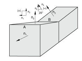
The feature angle is the angle formed between the normals of the two facets connected to an edge. The angles between facets are based on the initial configuration. A negative angle will result at concave meetings of facets. Figure 34.2.21 shows some examples of how the feature angle is calculated for different edges.
The feature angle for edge A is 90° (the angle betweenWhen you assign a feature angle criterion, geometric edges of solid bodies with feature angles greater than or equal to the specified angle are included in the general contact domain. The contact inclusion and exclusion options (discussed in “Defining general contact interactions in Abaqus/Standard,” Section 34.2.1) apply to both the surface-to-surface contact formulation and the edge-to-surface contact formulation (and further control which portions of surfaces may interact with either formulation). The sign of the feature angle is considered when determining whether or not a geometric feature edge should be included in the general contact domain. For example, if a cutoff feature angle of 20° were specified, edge A would be activated as a feature edge in the contact model (90° > 20°) but edge B would not be activated (25° < 20°). The cutoff feature angle cannot be set to less than 20°. Allowing a cutoff feature angle of less than 20° could severely degrade performance and would not affect the analysis results significantly compared to a cutoff angle of 20°.
Some aspects of the contact property assignment options apply only to the surface-to-surface formulation (see “Contact properties for general contact in Abaqus/Standard,” Section 34.2.3, for further discussion of contact properties for general contact). The edge-to-surface formulation always uses the penalty enforcement method and only involves displacement degrees of freedom. For example, the edge-to-surface formulation does not contribute to thermal gap conductance across a contact interface.
| Input File Usage: | *SURFACE PROPERTY ASSIGNMENT, PROPERTY=FEATURE EDGE CRITERIA surface, feature_angle_value |
If the surface name is omitted, a default surface that encompasses the entire general contact domain is assumed. |
| Abaqus/CAE Usage: | A feature angle criterion cannot be defined in Abaqus/CAE. |