Now you will define contact between regions of the model. There are two approaches that can be adopted to define contact interactions. The first is a manual approach that requires you to identify which surfaces will form part of the contact interactions and to define the individual contact pairs. An alternative approach is to let Abaqus/CAE automatically identify and define all potential contact pairs. The latter approach is desirable for complicated models containing many contact interactions. The automatic contact definition option is available only for three-dimensional Abaqus/Standard models.
In “Defining contact between regions of the model,” Section C.9, you will be given the option to define the contact interactions either manually (where you will use the surfaces defined in the following instructions) or automatically (in which case the surfaces defined below are not used; Abaqus/CAE will choose the surfaces automatically). For instructional purposes, however, you are encouraged to complete the surface definition instructions that follow regardless of the approach you choose to define the contact interactions.
When manually defining contact interactions, the first step is to create the surfaces that you will include later in interactions. It is not always necessary to create your surfaces in advance; if the model is simple or the surfaces easy to select, you can indicate the master and slave surfaces directly in the viewport as you create the interactions. However, in this tutorial it is easier to define the surfaces separately and then refer to the names of those surfaces when you create the interactions. You will define the following surfaces:
A surface named Pin that includes the outside surface of the pin.
Two surfaces named Flange-h and Flange-s that include the two flange faces that contact each other.
Two surfaces named Inside-h and Inside-s that include the inside surfaces of the flanges that contact the pin.
In this section you will define the outside surface of the pin. You will find it helpful to display only one part instance at a time while you select the surfaces to be defined.
To display only a single part instance in the assembly:
From the main menu bar, select View![]() Assembly Display Options.
Assembly Display Options.
The Assembly Display Options dialog box appears.
Click the Instance tab.
The part instances that you have created are listed with check marks in the Visible column. All the part instances are visible by default.
Click in the Visible column next to Hinge-hole-1 and Hinge-solid-1, and click Apply.
The hinge pieces disappear from the view.
To define a surface on the pin:
In the Model Tree, expand the Assembly container and double-click the Surfaces item.
The Create Surface dialog box appears.
In the dialog box, name the surface Pin and click Continue.
In the viewport, select the pin.
Click mouse button 2 in the viewport to indicate that you have finished selecting regions for the surface.
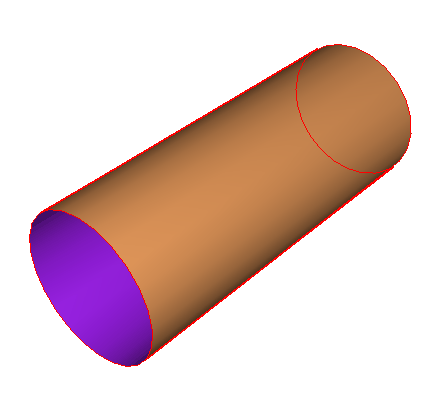
Each side of the hollow cylinder representing the pin has a different color associated with it. In Figure C37 the outside of the pin is colored brown and the inside of the pin is colored purple. The colors may be reversed on your model, depending on how you created the original sketch for the pin.
You must choose whether the surface consists of the inside or the outside of the cylinder. The outside surface contacts the two hinges and is the desired choice. From the buttons in the prompt area, click the color (Brown or Purple) associated with the outside surface.
Abaqus/CAE creates the desired surface called Pin and displays it underneath the Surfaces container in the Model Tree.
In this section you will define the surfaces on the hinge pieces needed to define contact between the two hinge pieces and between the hinge pieces and the pin.
To define the surfaces on the hinge pieces:
From the Assembly Display Options dialog box, change the visibility settings so that only Hinge-hole-1 is visible.
Abaqus/CAE displays only the hinge piece with the lubrication hole in the viewport.
In the Model Tree, double-click Surfaces underneath the Assembly container.
The Create Surface dialog box appears.
In the dialog box, name the surface Flange-h and click Continue.
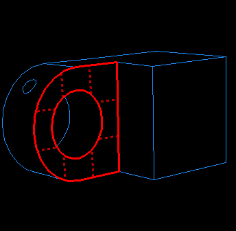
On the instance with the lubrication hole, select the face of the flange that contacts the other flange, as shown by the gridded face in Figure C38. (You may need to rotate the view to see this face clearly.)
When you have selected the desired face, click mouse button 2 to confirm your selection.
Abaqus/CAE creates the desired surface called Flange-h and displays it underneath the Surfaces container in the Model Tree.
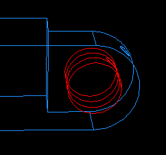
Create a surface called Inside-h that includes the cylindrical inner surface of the hinge piece with the lubrication hole, as shown in Figure C39. (You may need to zoom in on the view to select this face.)
Change the visibility settings so that only Hinge-solid-1 is visible.
Use similar techniques to create a surface called Flange-s that contains the corresponding face of the solid hinge piece's flange.
Finally, create a surface called Inside-s that includes the cylindrical inner surface of the solid hinge piece.
In the Assembly Display Options dialog box, click Defaults to return to the default visibility settings and click OK to close the dialog box.