Product: Abaqus/CAE
Benefits: Bottom-up meshing can now be used with orphan mesh models in addition to native geometry, and a new method—offset—is available for working with orphan meshes. The extrude method includes several new options for setting the extrusion depth and a new parameter that you can use to vary the thickness of the extruded element layers. You can now automatically create element sets for native or orphan meshes or extend existing sets in an orphan mesh model to include the bottom-up mesh elements.
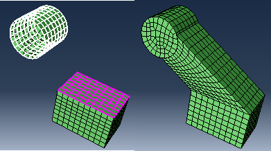
Description: You can now use bottom-up meshing to create new solid elements on an orphan mesh part. You can also work with dependent orphan mesh instances—the mesh changes are added to the mesh part. The sweep, extrude, and revolve bottom-up meshing methods can be used with either bottom-up meshing cells on native geometry or with orphan meshes. These methods work the same way for orphan meshes as they do for native meshes.
A new offset bottom-up method is available for use only with orphan meshes. The offset method in the Create Bottom-Up Mesh dialog box is very similar to the Offset (create solid layers) option in the Edit Mesh dialog box. Both methods add solid elements to an existing solid or shell orphan mesh.
The bottom-up extrude method now provides three options for selecting the extrusion depth:
Use vector length,
Specify, or
Project to target.
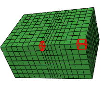
The bottom-up extrude method includes a new parameter, Bias ratio, that allows you to vary the thickness of the extruded elements from the source side to the end of the extruded depth. The bias ratio is the ratio of the thickness of the last layer of elements in the extruded mesh to the thickness of the first layer. A bias ratio of 1.0 has equal thickness for all extruded layers. Figure 128 shows an orphan mesh part that was extended by adding an extruded mesh with a bias ratio of 3.0. The layer of elements closest to the source side is 1/3 of the thickness of the last extruded layer. A bias ratio between zero and one would result in thicker layers at the source side and thinner ones at the end of the extrusion.
You can create element sets in either a native or an orphan mesh model containing the new bottom-up elements, or you can extend existing orphan mesh element sets to include newly created bottom-up elements. If you extend existing sets, the new elements added to those sets are included for section assignments and any other set-based functions. If you create new sets, you can create either a single set with all the bottom-up elements or create a separate set for each layer of elements. The element set controls are located in the Options area of the Create Bottom-Up Mesh dialog box.
Mesh module:
    MeshCreate Bottom-Up Mesh