
Product: Abaqus/Standard
“Sequentially coupled multiphysics analyses using predefined loads,” Section 16.2.2
“User subroutines index,” Section A.1 of the Abaqus User Subroutines Reference Manual
Eddy current problems:
involve coupling between electric and magnetic fields, which are solved for simultaneously;
solve Maxwell's equations describing electromagnetic phenomena under the low-frequency assumption that neglects the effects of displacement currents;
require the use of electromagnetic elements in the whole domain;
require that magnetic permeability is specified in the whole domain and electrical conductivity is specified in the conducting regions;
calculate as output variables, rate of Joule heating and intensity of magnetic body forces associated with eddy currents, and these output variables can be transferred to drive a subsequent heat transfer, coupled temperature-displacement, or stress/displacement analysis, thereby allowing for the coupling of electromagnetic fields with thermal and/or mechanical fields in a sequentially coupled manner;
allow for time-harmonic electromagnetic solutions only; and
can be solved using continuum elements in two- and three-dimensional space.
Eddy currents are generated in a metal workpiece when it is placed within a time-varying magnetic field. Joule heating arises when the energy dissipated by the eddy currents flowing through the workpiece is converted into thermal energy. This heating mechanism is usually referred to as induction heating; the induction cooker is an example of a device that uses this mechanism. The time-varying magnetic field is usually generated by a coil that is placed close to the workpiece. The coil carries either a known amount of total current or an unknown amount of current under a known potential (voltage) difference, alternating at a known frequency.
The eddy current analysis procedure is based on the assumption that a time-harmonic excitation with a certain frequency results in a time-harmonic electromagnetic response with the same frequency everywhere in the domain. In other words, both the electric and the magnetic fields oscillate at the same frequency as that of the alternating current in the coil.
The eddy current analysis provides output, such as Joule heat dissipation or magnetic body force intensity, that can be transferred to drive a subsequent heat transfer, coupled temperature-displacement, or stress/displacement analysis. This allows for modeling the interactions of the electromagnetic fields with thermal and/or mechanical fields in a sequentially coupled manner. See “Mapping thermal and magnetic loads,” Section 3.2.21, and “Sequentially coupled multiphysics analyses using predefined loads,” Section 16.2.2, for details.
Electromagnetic elements must be used to model the response of all the regions in an eddy current analysis including the coil, the workpiece, and the space in between and surrounding them. To obtain accurate solutions, the outer boundary of the space (surrounding the coil and the workpiece) being modeled must be at least a few characteristic length scales away from the device on all sides.
The electromagnetic elements use an element edge-based interpolation of the fields instead of the standard node-based interpolation. The user-defined nodes only define the geometry of the elements; and the degrees of freedom of the element are not associated with these nodes, which has implications for applying boundary conditions (see “Boundary conditions” below).
The electric and magnetic fields are governed by Maxwell's equations describing electromagnetic phenomena. The formulation is based on the low-frequency assumption, which neglects the displacement current correction term in Ampere's law. This assumption is appropriate when the wavelength of the electromagnetic waves corresponding to the excitation frequency is large compared to typical length scales over which the response is computed.
It is convenient to introduce a magnetic vector potential, ![]() , such that the magnetic flux density vector
, such that the magnetic flux density vector ![]() . The solution procedure seeks a time-harmonic electromagnetic response,
. The solution procedure seeks a time-harmonic electromagnetic response, ![]() , with frequency
, with frequency ![]() radians/sec when the system is subjected to a time-harmonic excitation of the same frequency; for example, through an impressed oscillating volume current density,
radians/sec when the system is subjected to a time-harmonic excitation of the same frequency; for example, through an impressed oscillating volume current density, ![]() . In the preceding expressions the vectors
. In the preceding expressions the vectors ![]() and
and ![]() represent the amplitudes of the magnetic vector potential and applied volume current density vector, respectively, while the exponential factors (with
represent the amplitudes of the magnetic vector potential and applied volume current density vector, respectively, while the exponential factors (with ![]() ) represent the corresponding phases. Under these assumptions, Maxwell's equations reduce to
) represent the corresponding phases. Under these assumptions, Maxwell's equations reduce to
![]()
The variational form of the above equation is
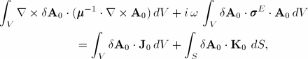
Abaqus/Standard solves the variational form of Maxwell's equations for the in-phase (real) and out-of-phase (imaginary) components of the magnetic vector potential. The other field quantities are derived from the magnetic vector potential.
The absolute value of magnetic permeability, ![]() , can be isotropic, orthotropic, or fully anisotropic (see “Magnetic permeability,” Section 25.5.3). The magnetic permeability can also depend on frequency, temperature, and/or predefined field variables. Only linear material properties are supported; magnetic permeability is assumed to be independent of the magnetic field,
, can be isotropic, orthotropic, or fully anisotropic (see “Magnetic permeability,” Section 25.5.3). The magnetic permeability can also depend on frequency, temperature, and/or predefined field variables. Only linear material properties are supported; magnetic permeability is assumed to be independent of the magnetic field, ![]() .
.
The electrical conductivity, ![]() , can be isotropic, orthotropic, or fully anisotropic (see “Electrical conductivity,” Section 25.5.1). The electrical conductivity can also depend on frequency, temperature, and/or predefined field variables. Ohm's law assumes that the electrical conductivity is independent of the electrical field,
, can be isotropic, orthotropic, or fully anisotropic (see “Electrical conductivity,” Section 25.5.1). The electrical conductivity can also depend on frequency, temperature, and/or predefined field variables. Ohm's law assumes that the electrical conductivity is independent of the electrical field, ![]() .
.
The eddy current analysis procedure provides the time-harmonic solution directly at a given excitation frequency. You can specify one or more excitation frequencies, one or more frequency ranges, or a combination of excitation frequencies and ranges.
| Input File Usage: | *ELECTROMAGNETIC, LOW FREQUENCY, TIME HARMONIC lower_freq1, upper_freq1, num_pts1 lower_freq2, upper_freq2, num_pts2 ... single_freq1 single_freq2 ... |
For example, the following input illustrates the simplest case of specifying excitation at a single frequency: *ELECTROMAGNETIC, LOW FREQUENCY, TIME HARMONIC single_freq1 |
In a time-harmonic eddy current analysis it is very common that large portions of the model consist of electrically nonconductive regions, such as air and/or a vacuum. In such cases it is well known that the associated stiffness matrix can be very ill-conditioned; i.e., it can have many singularities (Bíró, 1999). Abaqus uses a special iterative solution technique to prevent the ill-conditioned matrix from negatively impacting the computed electric and magnetic fields. The default implementation works well for many problems. However, there can be situations in which the default numerical scheme fails to converge or results in a noisy solution. In such cases adding a “small” amount of artificial electrical conductivity to the nonconductive domain may help regularize the problem and allow Abaqus to converge to the correct solution. The artificial electrical conductivity should be chosen such that the electromagnetic waves propagating through these regions undergo little modification and, in particular, do not experience the sharp exponential decay that is typical when such fields impinge upon a real conductor. It is recommended that you set the artificial conductivity to be about five to eight orders of magnitude less than that of any of the conductors in the model.
Initial values of temperature and/or predefined field variables can be specified. These values affect only temperature and/or field-variable-dependent material properties, if any. Initial conditions on the electric and/or magnetic fields cannot be specified in an eddy current analysis.
Electromagnetic elements use an element edge-based interpolation of the fields. The degrees of freedom of the element are not associated with the user-defined nodes, which only define the geometry of the element. Consequently, the standard node-based method of specifying boundary conditions cannot be used with electromagnetic elements. The method used for specifying boundary conditions for electromagnetic elements is described in the following paragraphs.
Boundary conditions in Abaqus typically refer to what are traditionally known as Dirichlet-type boundary conditions in the literature, where the values of the primary variable are known on the whole boundary or on a portion of the boundary. The alternative, Neumann-type boundary conditions, refer to situations where the values of the conjugate to the primary variable are known on portions of the boundary. In Abaqus Neumann-type boundary conditions are represented as surface loads in the finite-element formulation.
For electromagnetic boundary value problems, Dirichlet boundary conditions on an enclosing surface must be specified as ![]() , where
, where ![]() is the outward normal to the surface, as discussed in this section. Neumann boundary conditions must be specified as the surface current density vector,
is the outward normal to the surface, as discussed in this section. Neumann boundary conditions must be specified as the surface current density vector, ![]() , as discussed in “Loads” below.
, as discussed in “Loads” below.
In Abaqus Dirichlet boundary conditions are specified as magnetic vector potential, ![]() , on (element-based) surfaces that represent symmetry planes and/or external boundaries in the model; Abaqus computes
, on (element-based) surfaces that represent symmetry planes and/or external boundaries in the model; Abaqus computes ![]() for the representative surfaces. In applications where the electromagnetic fields are driven by a current-carrying coil that is close to the workpiece, the model may span a domain that is up to 10 times the characteristic length scale associated with the coil/workpiece assembly. In such cases, the electromagnetic fields are assumed to have decayed sufficiently in the far-field, and the value of the magnetic vector potential can be set to zero in the far-field boundary. On the other hand, in applications such as one where a conductor is embedded in a uniform (but varying time-harmonically) far-field magnetic field, it may be necessary to specify nonzero values of the magnetic vector potential on some portions of the external boundary. In this case an alternative method to model the same physical phenomena is to specify the corresponding unique value of surface current density,
for the representative surfaces. In applications where the electromagnetic fields are driven by a current-carrying coil that is close to the workpiece, the model may span a domain that is up to 10 times the characteristic length scale associated with the coil/workpiece assembly. In such cases, the electromagnetic fields are assumed to have decayed sufficiently in the far-field, and the value of the magnetic vector potential can be set to zero in the far-field boundary. On the other hand, in applications such as one where a conductor is embedded in a uniform (but varying time-harmonically) far-field magnetic field, it may be necessary to specify nonzero values of the magnetic vector potential on some portions of the external boundary. In this case an alternative method to model the same physical phenomena is to specify the corresponding unique value of surface current density, ![]() , on the far-field boundary (see “Loads” below).
, on the far-field boundary (see “Loads” below). ![]() can be computed based on known values of the far-field magnetic field.
can be computed based on known values of the far-field magnetic field.
In an eddy current analysis the boundary conditions are assumed to be time harmonic and are applied simultaneously to both the real and imaginary parts of the magnetic vector potential. It is not possible to specify Dirichlet boundary conditions on the real parts and Neumann boundary conditions on the imaginary parts and vice versa. Abaqus automatically restrains both the real and imaginary parts even if only one part is prescribed explicitly. The unspecified part is assumed to have a magnitude of zero.
A surface without any prescribed boundary condition corresponds to a surface with zero surface currents, or no loads.
When you prescribe the boundary condition on an element-based surface (see “Element-based surface definition,” Section 2.3.2), you must specify the surface name, the region type label (S), the boundary condition type label, an optional orientation name, the magnitude of the real part of the boundary condition, the direction vector for the real part of the boundary condition, the magnitude of the imaginary part of the boundary condition, and the direction vector for the imaginary part of the boundary condition. The optional orientation name defines the local coordinate system in which the components of the magnetic vector potential are defined. By default, the components are defined with respect to the global directions.
The specified vector components are normalized by Abaqus and, thus, do not contribute to the magnitude of the boundary condition.
Nonuniform boundary conditions can be defined with user subroutine UDEMPOTENTIAL.
| Input File Usage: | Use the following option to define both the real (in-phase) and imaginary (out-of-phase) parts of the boundary condition on element-based surfaces: |
*D EM POTENTIAL
surface name, S, bc type label, orientation, magnitude of real part, direction vector of real part, magnitude of imaginary part, direction vector of imaginary part
where the boundary condition type label (bc type label) can be MVP for a uniform boundary condition or MVPNU for a nonuniform boundary condition. |
An amplitude definition can be used to specify the amplitude of a boundary condition as a function of frequency (“Amplitude curves,” Section 32.1.2).
| Input File Usage: | Use both of the following options: |
*AMPLITUDE, NAME=name *D EM POTENTIAL, AMPLITUDE=name |
The following types of electromagnetic loads can be applied in an eddy current analysis (see “Prescribing electromagnetic loads for eddy current analyses” in “Electromagnetic loads,” Section 32.4.5, for details):
Element-based distributed volume current density vector, ![]()
Surface-based distributed surface current density vector, ![]()
| Input File Usage: | Use the following options to define real and imaginary components of the current density vectors: |
*DECURRENT, REAL or IMAGINARY *DSECURRENT, REAL or IMAGINARY |
An amplitude definition can be used to specify the amplitude of a load as a function of frequency (“Amplitude curves,” Section 32.1.2).
| Input File Usage: | Use both of the following options: |
*AMPLITUDE, NAME=name *DECURRENT or *DSECURRENT, REAL or IMAGINARY, AMPLITUDE=name |
Predefined temperature and field variables can be specified in an eddy current analysis. These values affect only temperature and/or field-variable-dependent material properties, if any. See “Predefined fields,” Section 32.6.1.
Magnetic permeability (see “Magnetic permeability,” Section 25.5.3) must be specified everywhere in the model. Electrical conductivity (see “Electrical conductivity,” Section 25.5.1) must be specified in conductor regions. All other material properties are ignored in an eddy current analysis. Only linear material properties are supported. Both magnetic permeability and electrical conductivity can be functions of frequency, predefined temperature, and field variables.
Electromagnetic elements must be used to model all regions in an eddy current analysis. Unlike conventional finite elements, which use node-based interpolation, these elements use edge-based interpolation with the tangential components of the magnetic vector potential along element edges serving as the primary degrees of freedom.
Electromagnetic elements are available in Abaqus/Standard in two dimensions (planar only) and three dimensions (see “Choosing the appropriate element for an analysis type,” Section 26.1.3). The planar elements are formulated in terms of an in-plane magnetic vector potential, thereby the magnetic flux density and magnetic field vectors only have an out-of-plane component. The electric field and the current density vectors are in-plane for the planar elements.
Eddy current analysis provides output only to the output database (see “Output to the output database,” Section 4.1.3). Output to the data (.dat) file and to the results (.fil) file is not available. The components of the vector variables are output with respect to the global directions, even if the underlying material is specified in a local system using an orientation. For the first four vector quantities listed below (which are derived from the magnetic vector potential and the constitutive equations), the magnitude and components of the real and imaginary parts are output.
EMB | Magnitude and components of the magnetic flux density vector, |
EMH | Magnitude and components of the magnetic field vector, |
EME | Magnitude and components of the electric field vector, |
EMCD | Magnitude and components of the eddy current vector, |
EMBF | Magnetic body force intensity vector (force per unit volume per unit time) due to flow of current. |
EMJH | Rate of Joule heating (amount of heat per unit volume per unit time) due to flow of current. |
ELJD | Total rate of Joule heating (amount of heat per unit time) due to flow of current in an element. |
ALLJD | Rate of Joule heating (amount of heat per unit time) summed over the model or an element set. |
*HEADING
…
*MATERIAL, NAME=mat1
*MAGNETIC PERMEABILITY
Data lines to define magnetic permeability
*ELECTRICAL CONDUCTIVITY
Data lines to define electrical conductivity in the conductor region
**
*STEP
*ELECTROMAGNETIC, LOW FREQUENCY, TIME HARMONIC
Data line to specify excitation frequencies
*D EM POTENTIAL
Data lines to define boundary conditions on magnetic vector potential
*DECURRENT
Data lines to define element-based distributed volume current density vector
*DSECURRENT
Data lines to define surface-based distributed surface current density vector
*OUTPUT, FIELD or HISTORY
Data lines to request element-based output
*ENERGY OUTPUT
Data line to request whole model Joule heat dissipation output
*END STEP