Product: Abaqus/Standard
This example illustrates the use of connectors to model the deployment of a trailing edge flap mechanism in an aircraft.
The trailing edge flap mechanism is a critical component of an aircraft. The shape and positioning of the trailing edge flaps are important determinants of the aircraft's lift and aerodynamic behavior.
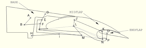
The trailing edge flap structure in this example problem consists of three flaps, BASE, MIDFLAP, and ENDFLAP; and these flaps are connected to each other by arms, which are rigid links pinned to the flaps at different points. The configuration of the flaps is illustrated in Figure 4.1.9–1. There are nine arms used in the model: ARM AB, ARM BF, ARM DEFG, ARM EI, ARM HIM, ARM JK, ARM MLJ, ARM NK, and ARM PO. BASE, MIDFLAP, and ENDFLAP are modeled as display bodies; and the arms are modeled as rigid truss members. MIDFLAP and ENDFLAP are deployed by rotating ARM AB pinned on BASE at point A.
The bodies in Figure 4.1.9–1 are connected as follows:
JOIN connector elements are used to connect the arms at their endpoints to BASE, MIDFLAP, and ENDFLAP. The endpoints of some arms are connected to other arms instead of being connected to the flaps. ARM AB is connected to ARM BF at B. ARM BF and ARM EI are connected to ARM DEFG at F and E, respectively. ARM EI and ARM MLJ are connected to ARM HIM at I and M, respectively. ARM MLJ is connected to ARM JK at J, and ARM MLJ is connected to MIDFLAP at L, which is not one of the endpoints of ARM MLJ.
LINK connector elements are used to rigidly fix the positions of the pivot points on the flaps. These link connectors are called LINK GL, LINK GN, LINK GP, LINK KO, LINK LN, and LINK LP. These additional link connectors are necessary to support BASE, MIDFLAP, and ENDFLAP because these flaps are modeled as display bodies and not as deformable or rigid bodies. LINK GL, LINK GN, LINK GP, LINK LN, and LINK LP are used to position points G, L, N, and P on MIDFLAP; and LINK KO is used to position points K and O on ENDFLAP.
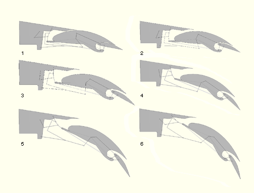
To deploy the flap, we fix BASE in space by fixing points A, D, and H and rotate ARM AB 90 degrees about point A. One analysis models plasticity effects in some of the connectors.
The rotation of ARM AB results in the deployment of MIDFLAP and ENDFLAP. Figure 4.1.9–2 contains a series of illustrations showing the positions of the flaps at the beginning and end of the analysis and also at some intermediate instants.
Python replay file for constructing the trailing edge flap mechanism model in Abaqus/CAE.
Trailing edge flap mechanism model.
Trailing edge flap mechanism model with connector plasticity.