When you choose Face from the Create Partition dialog box, the Method list displays the following methods for partitioning faces:
![]() Sketch planar partition
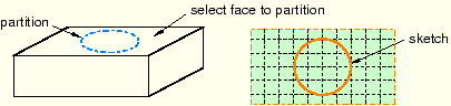
Sketch planar partition
Partition a selected face by sketching a partition with the Sketcher, as shown in Figure 67–8. For detailed instructions, see “Using the sketch method to partition faces,” Section 67.6.1.
You can sketch directly on the face to be partitioned, or you can sketch on a second face or datum plane and then project the sketch onto the face that you want to partition. For an example of projecting a sketch from a datum plane, see “Using the Datum toolset in the Part module,” Section 11.16.1.
![]() Shortest path between 2 points
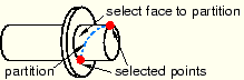
Shortest path between 2 points
Partition the face along the shortest path connecting two selected points; the resulting partition will be curved if the face being partitioned is curved, as shown in Figure 67–9. You can select points that are not associated with the face being partitioned; for example, the points can be located on a different face or even a different part instance. For detailed instructions, see “Using the shortest path method to partition faces,” Section 67.6.2.
![]() Use datum plane
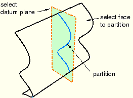
Use datum plane
Partition a face using the intersection with the extension of a datum plane, as shown in Figure 67–10. For detailed instructions, see “Using the datum plane method to partition faces,” Section 67.6.3.
![]() Curved path normal to 2 edges
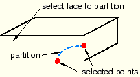
Curved path normal to 2 edges
Partition the face along a Bézier curve that is normal to two of the face's edges, as shown in Figure 67–11. Position the curve by selecting two points anywhere along the two edges. The arc subtended by the two edges must be less than 180°. For detailed instructions, see “Using the curved path method to partition a face,” Section 67.6.4.
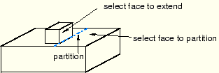
![]() Extend another face
Extend another face
Partition the face using the intersection with the extension of another face, as shown in Figure 67–12. The face being extended can be either planar, cylindrical, conical, or spherical; and it need not belong to the part containing the face to be partitioned. For detailed instructions, see “Using the extended face method to partition faces,” Section 67.6.5.
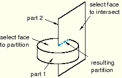
![]() Intersect by other faces
Intersect by other faces
Partition the face using the intersection of the target face with one or more other faces, as shown in Figure 67–13. The faces can be intersecting or tangential. For detailed instructions, see “Using the intersection method to partition faces,” Section 67.6.6.
![]() Auto-partition
Auto-partition
When you mesh a face with quadrilateral elements using the free meshing technique, the Mesh module internally partitions the face into regions with three to five logical sides before meshing the face. For more information, see “Free meshing with quadrilateral and quadrilateral-dominated elements,” Section 17.10.2. However, if you want to view and perhaps modify the automatically generated regions before generating the mesh, you can use the auto-partitioning tool to partition the face without meshing it. This tool is available only in the Mesh module. For detailed instructions, see “Using the automatic generation method to partition faces,” Section 67.6.7.