Product: Abaqus/Standard
This example verifies and illustrates the use of the extended finite element method (XFEM) in Abaqus/Standard to predict dynamic crack propagation of a beam with an offset edge crack. The specimen is subjected to a mixed-mode impact loading. Both two- and three-dimensional models are studied. The crack paths and crack initiation angles presented are compared to the experimental results of John and Shah (1990).
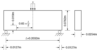
A beam with an offset edge crack is studied. The specimen, shown in Figure 1.19.31, has a length of 0.2286 m, a thickness of 0.0254 m, and a width of 0.0762 m. The distance between supports is 0.2032 m. To induce a mixed-mode fracture, an initial crack with a length of 0.019 m is made at an offset distance of 0.06604 m measured from the midspan in the specimen. A velocity boundary condition is imposed at the midspan of the specimen to simulate a dynamic impact:
![]()
The material data for the bulk material properties in the enriched elements are ![]() = 31.37 GPa,
= 31.37 GPa, ![]() = 2400 kg/m3, and
= 2400 kg/m3, and ![]() = 0.2.
= 0.2.
The response of cohesive behavior in the enriched elements in the model is specified. The maximum principal stress failure criterion is selected for damage initiation, and an energy-based damage evolution law based on a power law fracture criterion is selected for damage propagation. The relevant material data are as follows: ![]() = 10.45 MPa,
= 10.45 MPa, ![]() = 19.58 N/m,
= 19.58 N/m, ![]() = 19.58 N/m,
= 19.58 N/m, ![]() = 19.58 N/m,
= 19.58 N/m, ![]() = 1.0,
= 1.0, ![]() = 1.0, and
= 1.0, and ![]() = 1.0.
= 1.0.
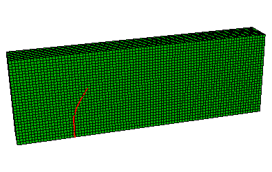
Figure 1.19.32 shows the crack profile when ![]() = 1.3 × 10⁻³ s. The crack propagates at an angle of 58°, which is in reasonable agreement with the experimental result of 60°.
= 1.3 × 10⁻³ s. The crack propagates at an angle of 58°, which is in reasonable agreement with the experimental result of 60°.
Two-dimensional plane strain model under mixed-mode impact loading.
Three-dimensional tetrahedron model under mixed-mode impact loading.
Three-dimensional brick model with reduced integration under mixed-mode impact loading.
Script to generate the three-dimensional brick model with reduced integration under mixed-mode impact loading in Abaqus/CAE simulated using the XFEM-based cohesive segments approach.