Product: Abaqus/Standard
This example verifies and illustrates the use of the extended finite element method (XFEM) in Abaqus/Standard to predict crack initiation and propagation due to stress concentration in a plate with a hole. The specimen is subjected to pure Mode I loading. The results presented are compared to the available analytical solution.
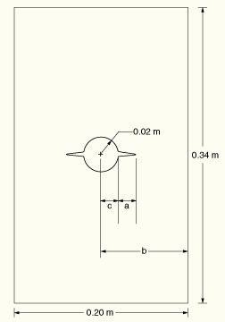
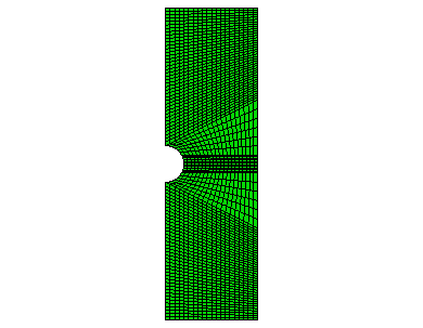
A plate with a circular hole is studied. The specimen, shown in Figure 1.19.2–1, has a length of 0.34 m, a thickness of 0.02 m, a width of 0.2 m, and a hole radius of 0.02 m, under pure Mode I loading. Figure 1.19.2–1 defines the dimensions used to calculate the variation of crack length, ![]() : a is the crack length, b is half the specimen width, and c is the hole radius. Equal and opposite displacements are applied at both ends in the longitudinal direction. The maximum displacement value is set equal to 0.00055 m. To examine the mesh sensitivity, three different mesh discretizations of the same geometry are studied. Symmetry conditions reduce the specimen to a half model. The original mesh, as depicted in Figure 1.19.2–2, has 2060 plane strain elements. The second mesh has four times as many elements as the original one, while the third mesh has sixteen times as many elements as the original one.
: a is the crack length, b is half the specimen width, and c is the hole radius. Equal and opposite displacements are applied at both ends in the longitudinal direction. The maximum displacement value is set equal to 0.00055 m. To examine the mesh sensitivity, three different mesh discretizations of the same geometry are studied. Symmetry conditions reduce the specimen to a half model. The original mesh, as depicted in Figure 1.19.2–2, has 2060 plane strain elements. The second mesh has four times as many elements as the original one, while the third mesh has sixteen times as many elements as the original one.
The material data for the bulk material properties in the enriched elements are ![]() GPa and
GPa and ![]() = 0.3.
= 0.3.
The response of cohesive behavior in the enriched elements in the model is specified. The maximum principal stress failure criterion is selected for damage initiation, and an energy-based damage evolution law based on a BK law criterion is selected for damage propagation. The relevant material data are as follows: ![]() MPa,
MPa, ![]() × 103 N/m,
× 103 N/m, ![]() × 103 N/m, and
× 103 N/m, and ![]() .
.
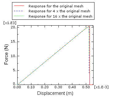
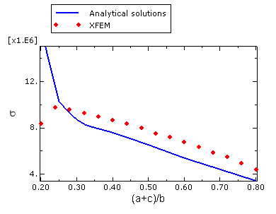
Figure 1.19.2–3 shows plots of the prescribed displacement versus the corresponding reaction force with different mesh discretizations. The figure clearly illustrates the convergence of the response to the same solution with mesh refinement. A plot of the applied stress versus the variation of crack length is presented in Figure 1.19.2–4 and compared with the analytical solution of Tada et al. (1985). The agreement is better than 10% except when the crack length is small, in which case the stress singularity ahead of the crack is not considered by the XFEM approach. However, as indicated in this figure, the crack initiates (i.e., ![]() ) when the applied stress,
) when the applied stress, ![]() , reaches a level of 8.37 MPa, giving a ratio of
, reaches a level of 8.37 MPa, giving a ratio of ![]() equal to 2.63. This value is in close agreement with the stress concentration factor of 2.52 obtained analytically for the same geometry.
equal to 2.63. This value is in close agreement with the stress concentration factor of 2.52 obtained analytically for the same geometry.
Abaqus/Standard two-dimensional plane strain model with a hole under pure Mode I loading.
Script to generate the two-dimensional plane strain model with a hole under pure Mode I loading in Abaqus/CAE.