Product: Abaqus/Standard
This example verifies and illustrates the use of the extended finite element method (XFEM) in Abaqus/Standard to predict crack initiation and propagation of a single-edge notch in a specimen along an arbitrary path by modeling the crack as an enriched feature. Both two- and three-dimensional models are studied. The specimen is subjected to loadings ranging from pure Mode I to pure Mode II to mixed-mode. The results presented are compared to the available analytical solutions and those obtained using cohesive elements.
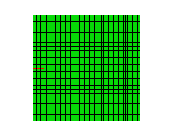
Two single-edge notch specimens are studied. The first specimen is shown in Figure 1.19.1–1 and has a length of 3 m, a thickness of 1 m, a width of 3 m, and an initial crack length of 0.3 m, loaded under pure Mode I loading. Equal and opposite displacements are applied at both ends in the longitudinal direction. The maximum displacement value is set equal to 0.001 m. The second specimen has a length of 6 m, a thickness of 1 m, a width of 3 m, and an initial crack length of 1.5 m, loaded under pure Mode II or mixed-mode loading. Equal and opposite displacements are applied at both ends in the width direction under pure Mode II loading, while equal and opposite displacements are applied at both ends in both the longitudinal and width directions under mixed-mode loading. The maximum displacement value is set equal to 0.0035 m.
The material data for the bulk material properties in the enriched elements are ![]() GPa and
GPa and ![]() .
.
The response of cohesive behavior in the enriched elements in the model is specified. The maximum principal stress failure criterion is selected for damage initiation; and a mixed-mode, energy-based damage evolution law based on a power law criterion is selected for damage propagation. The relevant material data are as follows: ![]() MPa,
MPa, ![]() × 103 N/m,
× 103 N/m, ![]() × 103 N/m,
× 103 N/m, ![]() 42.2× 10³ N/m, and
42.2× 10³ N/m, and ![]() .
.
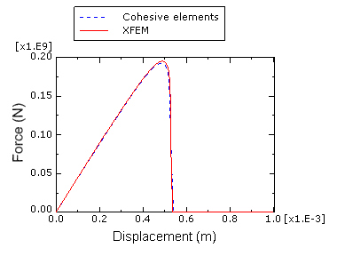
Figure 1.19.1–2 shows plots of the prescribed displacement versus the corresponding reaction force under the pure Mode I loading compared with the results obtained using cohesive elements. The results displayed are from the two-dimensional plane strain analyses. The results obtained using the XFEM method agree well with those obtained using cohesive elements. The results from the equivalent three-dimensional models show similar agreement.
Under the pure Mode II or mixed-mode loading, the crack will no longer propagate along a straight path and will instead propagate along a path based on the maximum tangential stress criterion according to Erdogan and Sih (1963). The direction of crack propagation is given by
Abaqus/Standard two-dimensional plane strain model with reduced integration under pure Mode I loading.
Abaqus/Standard two-dimensional plane strain model under pure Mode I loading.
Abaqus/Standard two-dimensional plane stress model with reduced integration under pure Mode I loading.
Abaqus/Standard two-dimensional plane stress model under pure Mode I loading.
Abaqus/Standard three-dimensional tetrahedron model under pure Mode I loading.
Abaqus/Standard three-dimensional brick model with reduced integration under pure Mode I loading.
Abaqus/Standard three-dimensional brick model under pure Mode I loading.
Abaqus/Standard two-dimensional plane strain model with reduced integration under pure Mode II loading.
Abaqus/Standard two-dimensional plane strain model under pure Mode II loading.
Abaqus/Standard two-dimensional plane stress model with reduced integration under pure Mode II loading.
Abaqus/Standard two-dimensional plane stress model under pure Mode II loading.
Abaqus/Standard three-dimensional tetrahedron model under pure Mode II loading.
Abaqus/Standard three-dimensional brick model with reduced integration under pure Mode II loading.
Abaqus/Standard three-dimensional brick model under pure Mode II loading.
Abaqus/Standard two-dimensional plane strain model with reduced integration under mixed-mode loading.
Abaqus/Standard two-dimensional plane strain model under mixed-mode loading.
Abaqus/Standard two-dimensional plane stress model with reduced integration under mixed-mode loading.
Abaqus/Standard two-dimensional plane stress model under mixed-mode loading.
Abaqus/Standard three-dimensional tetrahedron model under mixed-mode loading.
Abaqus/Standard three-dimensional brick model with reduced integration under mixed-mode loading.
Abaqus/Standard three-dimensional brick model under mixed-mode loading.
Script to generate the two-dimensional plane strain model under mixed-mode loading in Abaqus/CAE.
Script to generate the three-dimensional brick model under mixed-mode loading in Abaqus/CAE.